Interesting Trevor! However I don't think Pre War civilian bikes have any relevance to the enquiry? Ron
email (option): ronpier@talk21.com
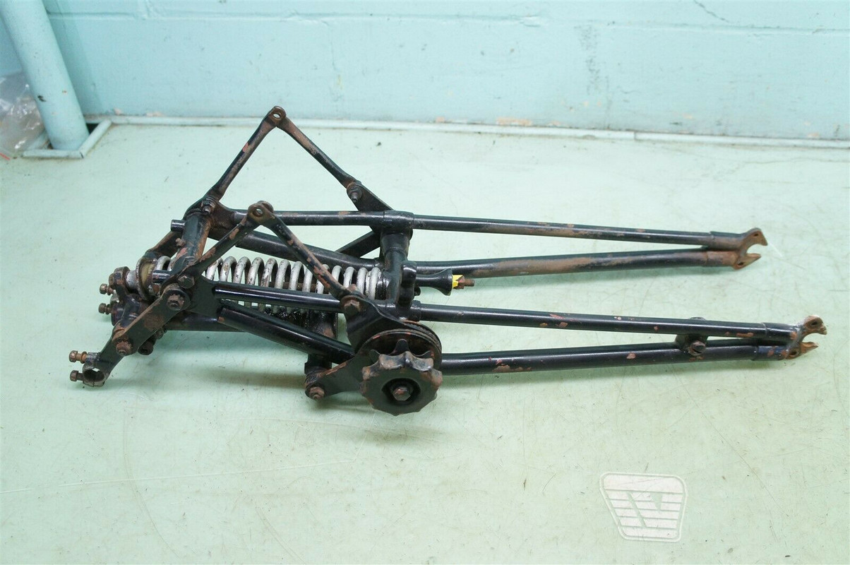
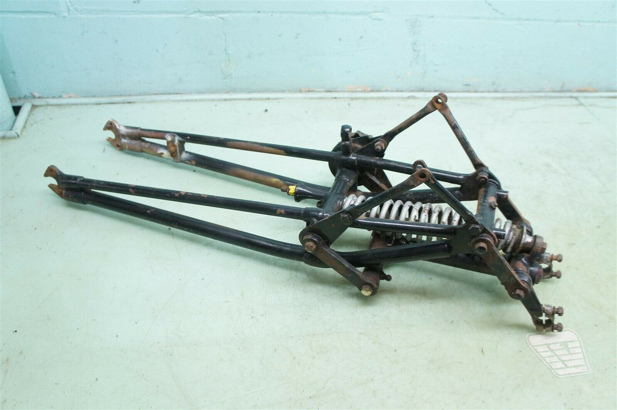
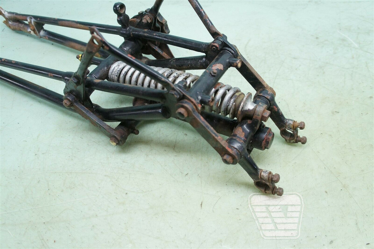
I decided to make a deal for these forks. They seem to fit the bill.... by the photos and descriptions of what should be on my 43.
As long as they are nice when they are delivered I will be happy with the deal I was able to make for them..
Then I would say the build can begin...
email (option): wadeschields@mindspring.com
I disappeared for a bit there but I am back (I hope) been crazy busy with work and life so time has been short.... I managed to find a free shed on facebook marketplace ... I little rough but I had it moved to my place for a good price and then fixed and replaced the bad parts , painted , insulated , put in a window for light and an AC unit . Hung LED lighting , a stereo and covered the walls with spare drywall and moved the WM20 in to my dedicated , one bike at a time, workshop.... Now the fun can begin.
Strip it down and put it back together again will be the plan
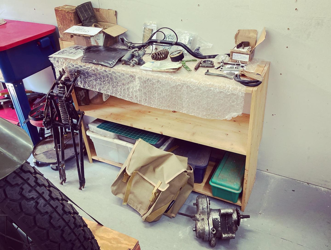

Wow! very good. indeed, let the fun start! succes.:+1:
email (option): info@wetblast.nl
Great shed...Somewhere 'proper' to work vastly increases the chances of success I'd say...Music is an essential as well IMO...In my case the duller the job (rubbing down components), the louder the music...:laughing: ....
That looks like a nice set of replacement forks you've bought and I'm sure they will work out to be the best course of action...Keep us posted on progress!...Ian
email (option): ian@wright52.plus.com
Do not take any chances with those forks
Too many times I have been at an event where the fork tubes fractured with very un-prety results for both rider & mount.
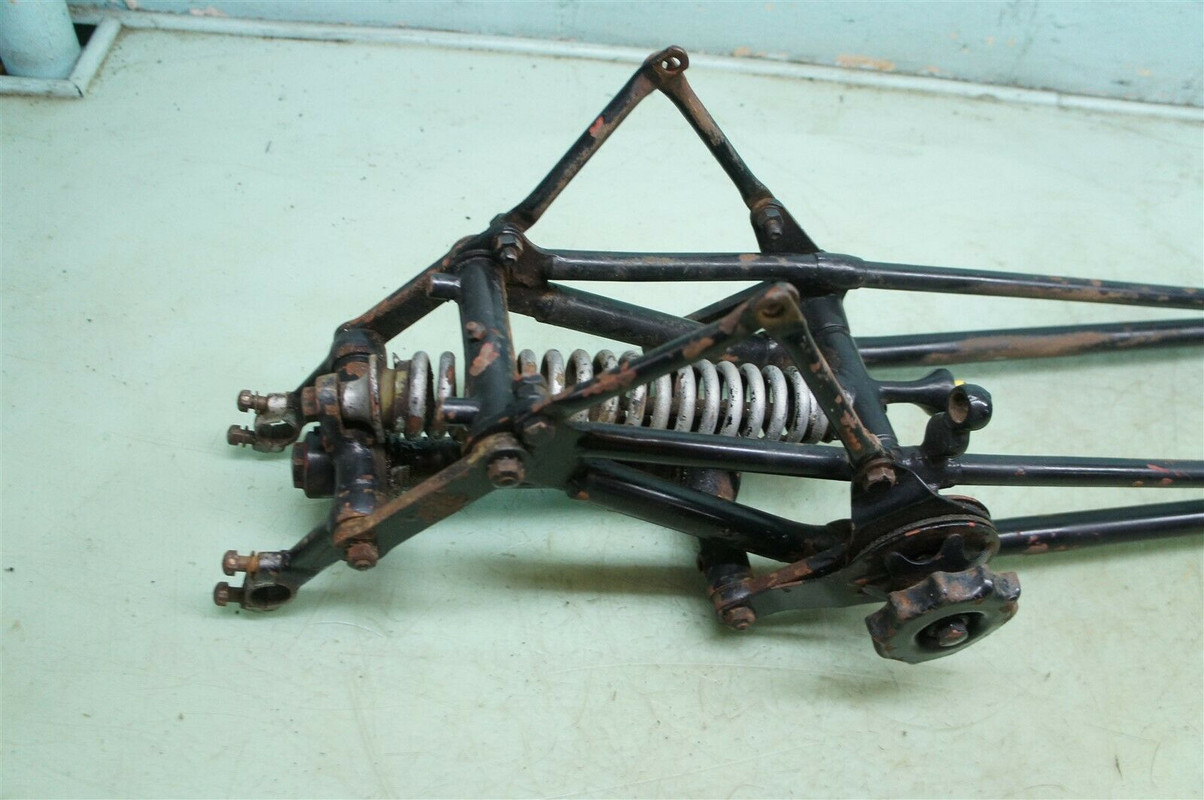
So have then grit blasted and crack tested at a minimum, X-rays are even better.
Particular close attention to the joints between the forgings & the tubes.
Bad enough for an old fart like me but a disaster if you end up being unable to work for months.
As you are probably going to have them painted in kakahi of some kind to match the bike then the only extra cost is the actual testing.
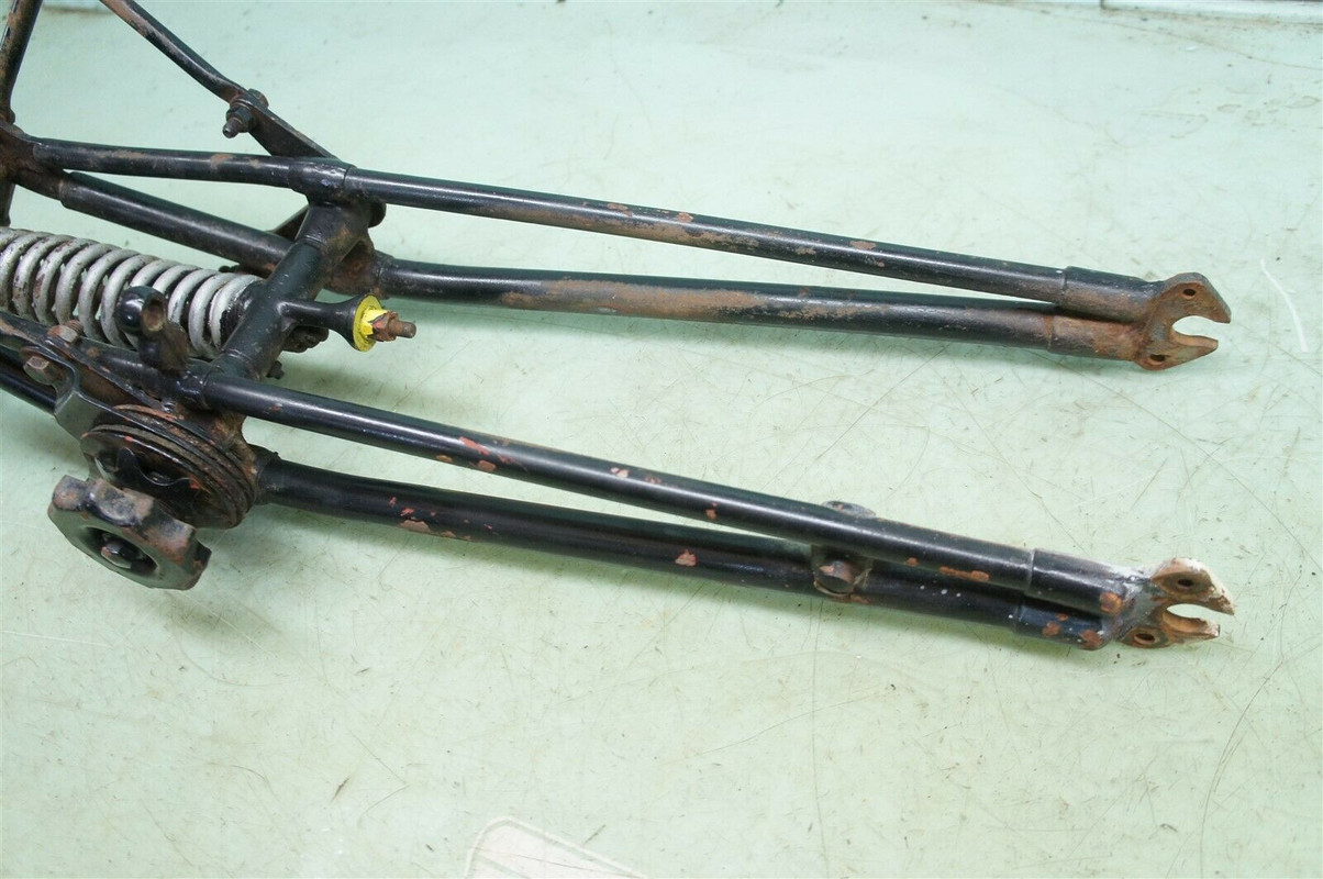
The tubes were furnace braized into the fittings so you should see a nice ring of yellow around the steel
If it is broken or shows any signs of corrosion then it is off to the frame man .
Get local friction discs and avoid NOS or ebay / amazon as there is a lot of stuff out there that has well & truely passed it's use by date and can crumble in use .
Having ridden 450 Km back from a rally with no damping it makes bull riding look smooth & easy.
From memory I used A 65 discs for the steering and ended up getting some custom cut of the forks .
Well I havent been here for awhile but have recently picked up a few more parts and am currently testing mag for spark but that is really all I have been able to do on my project for the last year or so... Just wanted to say hello and feel alive and well... Just been busy with life ...
email (option): wadeschields@mindspring.com
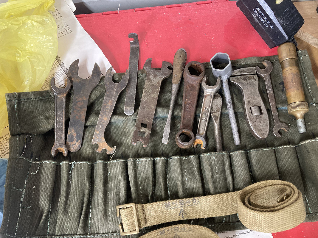
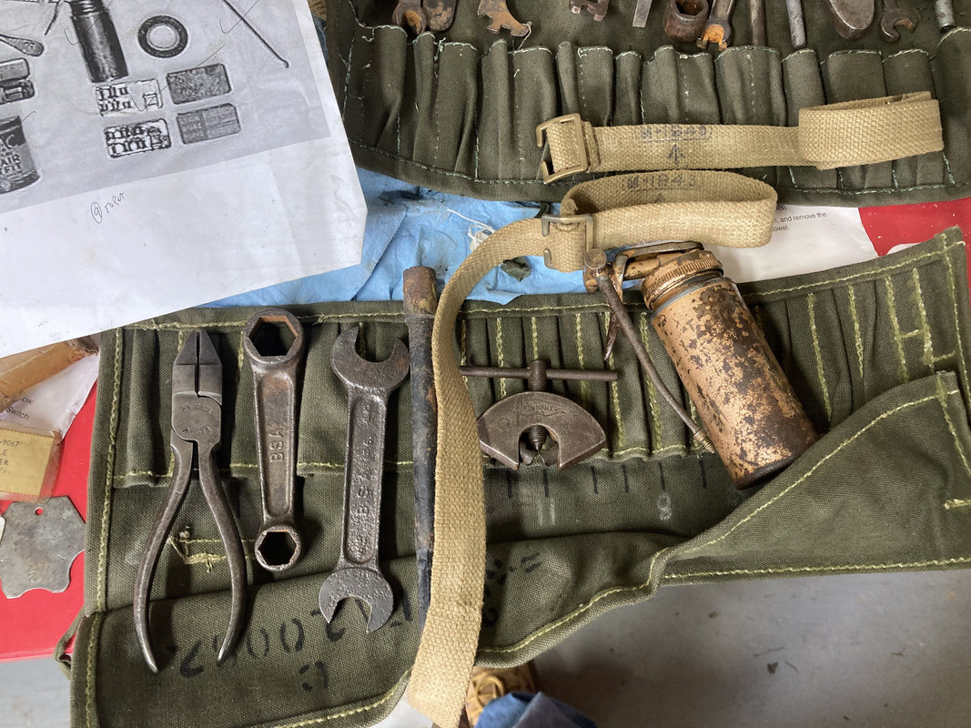
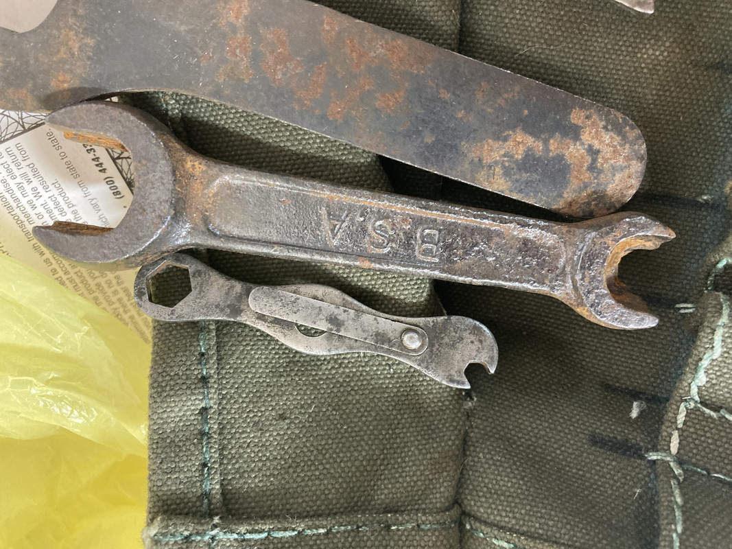
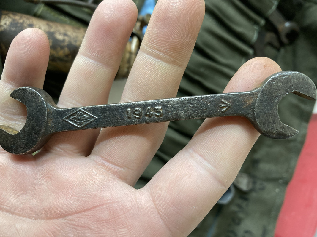
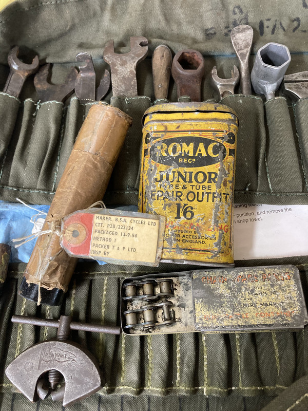
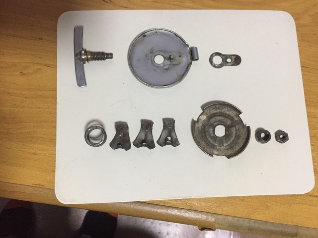
Looking over my tool kit and I have some questions
Here is what I have
email (option): wadeschields@mindspring.com
Here is what I see missing. Maybe more..
What are those two pieces that arnt checked?
Is that just electrical tape?
What is that small straight bit at the right side of the picture?
If no check mark then I dont have it
email (option): wadeschields@mindspring.com
Where does the photo come from ? The black circle is simply cloth insulating tape, isn't it ? Listed as 1/2" wide and a 4 oz. roll although that sounds like a large one. Norton listed 1/2" wide x 2 oz. roll and then illustrated a Dunlop tin which can only be the 10 yards x 5/8" type, based on scaling it up. Any roll of half-inchish black cotton adhesive tape would seem to comply.
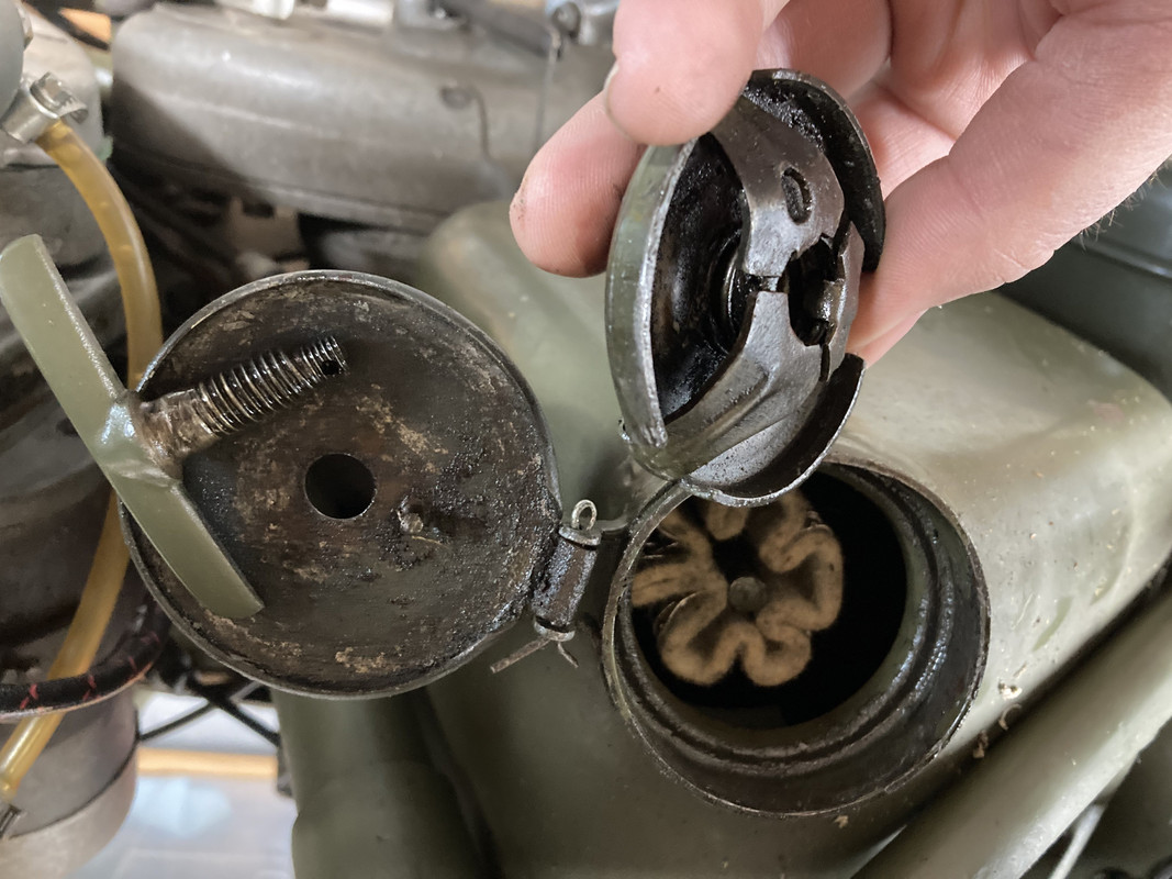
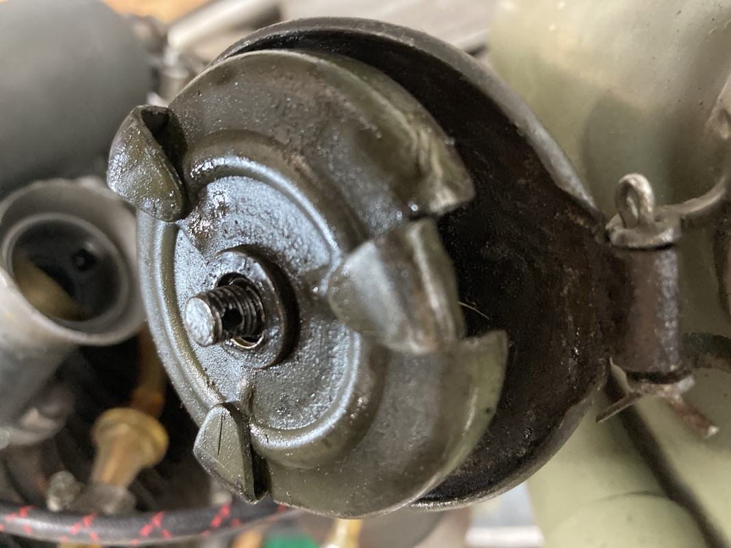
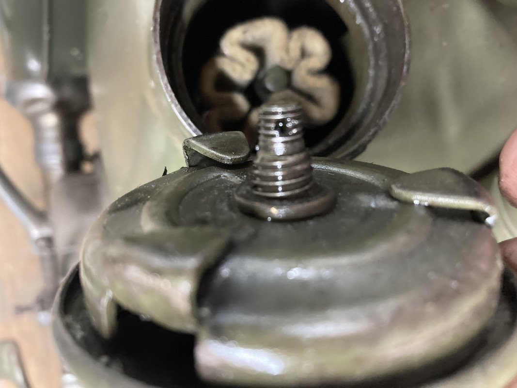
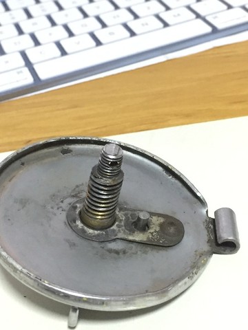
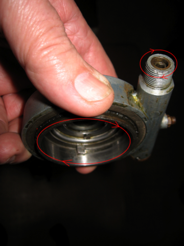
And while I was contemplating the tool kit (and avoiding Gardening with my wife) I took a look at the oil tank cap that has never locked when closing ... Assuming it was broken or missing something. So I took some photos to try to compare what I have with what I might find on the interweb... After unscrewing it and looking it over I noticed the nipple on the underside of the cap . That wasnt locking into anything and the mechanism was just spinning around... I thought I might be missing something... Then it dawned on me . the previous owner had put the thing together upside down !!! . Put it back on correctly and voila.. It locks!! Yeah!!! But now it seems I am missing a nut and a cotter pin. Is the nut just a normal whitworth nut with holes in it for the cotter pin? Does anyone have one they can spare? Otherwise I'll have to make one. I have a box of assorted cotter pins so one of those might fit .
Anything I am not grasping here?
email (option): wadeschields@mindspring.com
email (option): wadeschields@mindspring.com
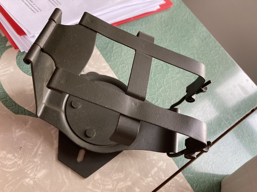
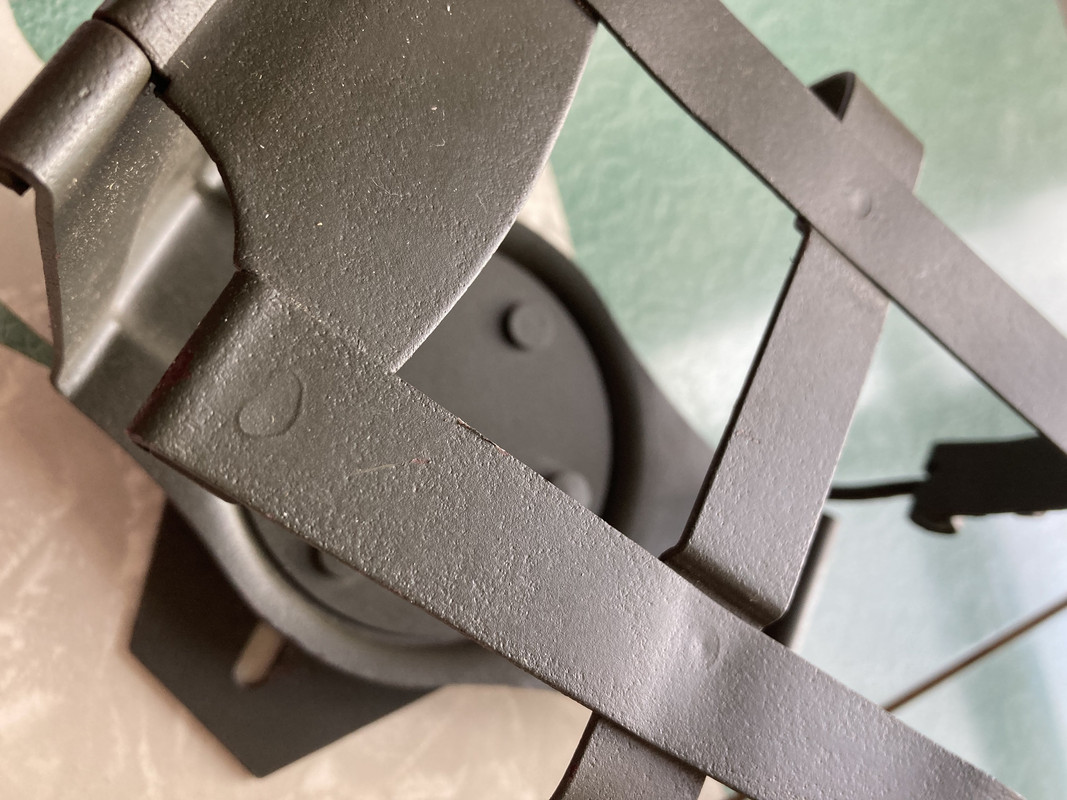
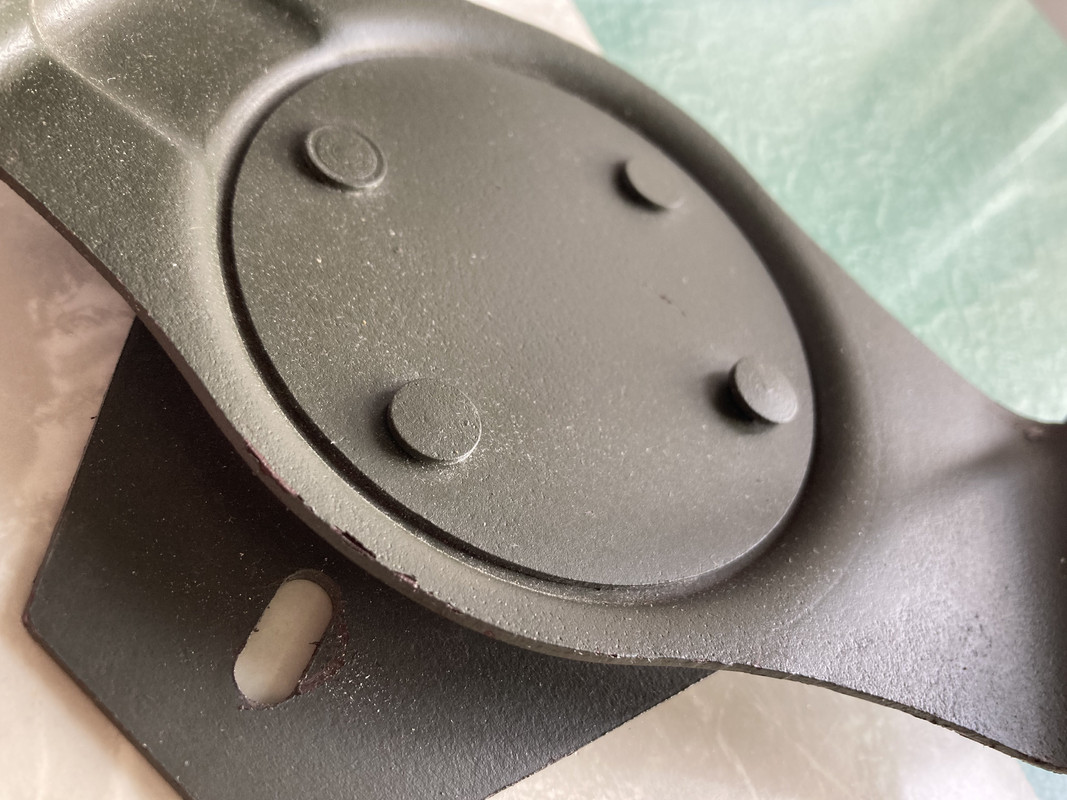
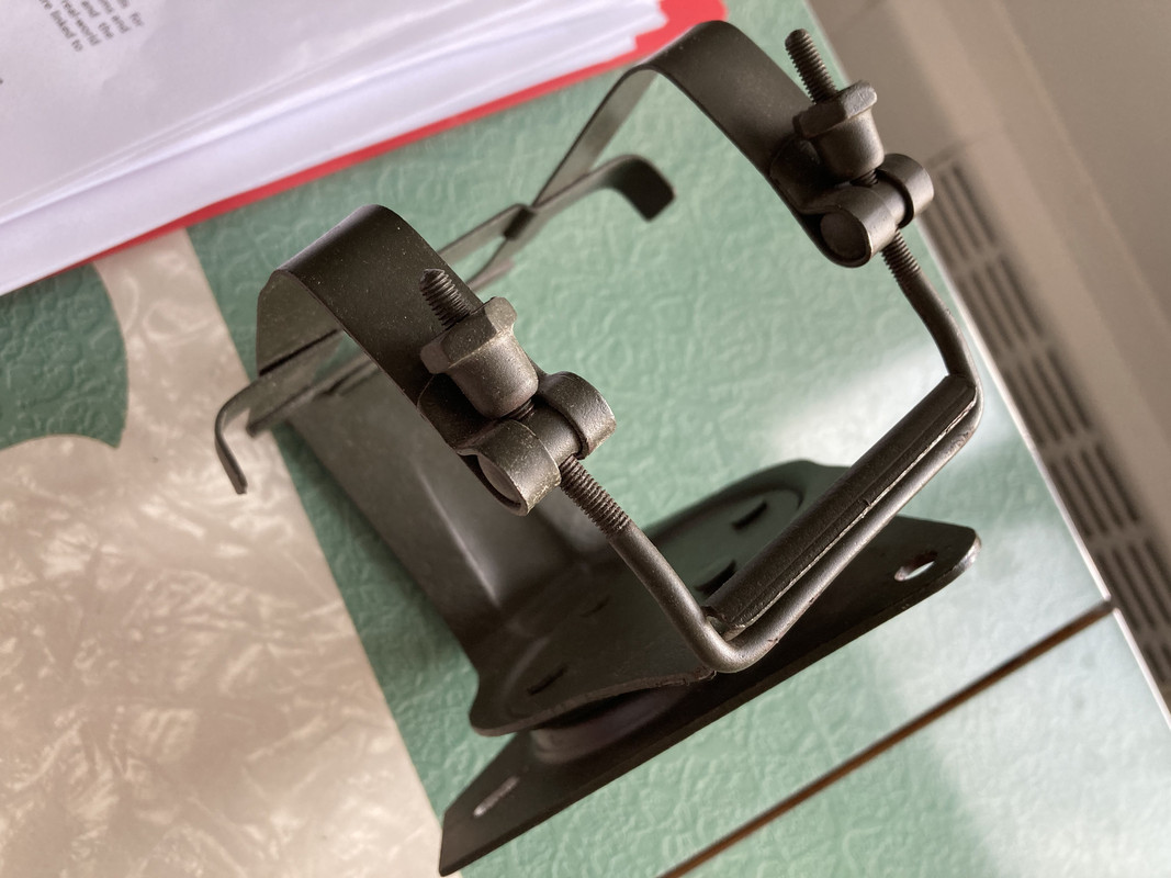
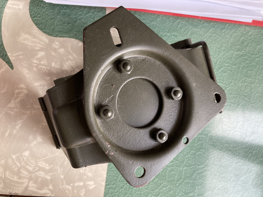
Almost my last question. So I picked up this battery box for 50 bucks on Ebay from someone in Washington state that was selling a bunch of WM20 parts . It arrived today but how do I know if its a repop or original... Kinda have a feeling its not original
email (option): wadeschields@mindspring.com
4th and last question for today...
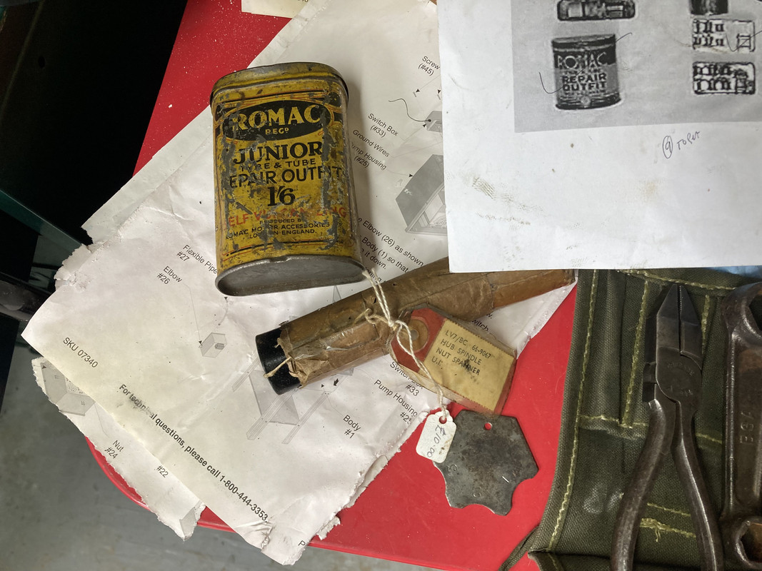
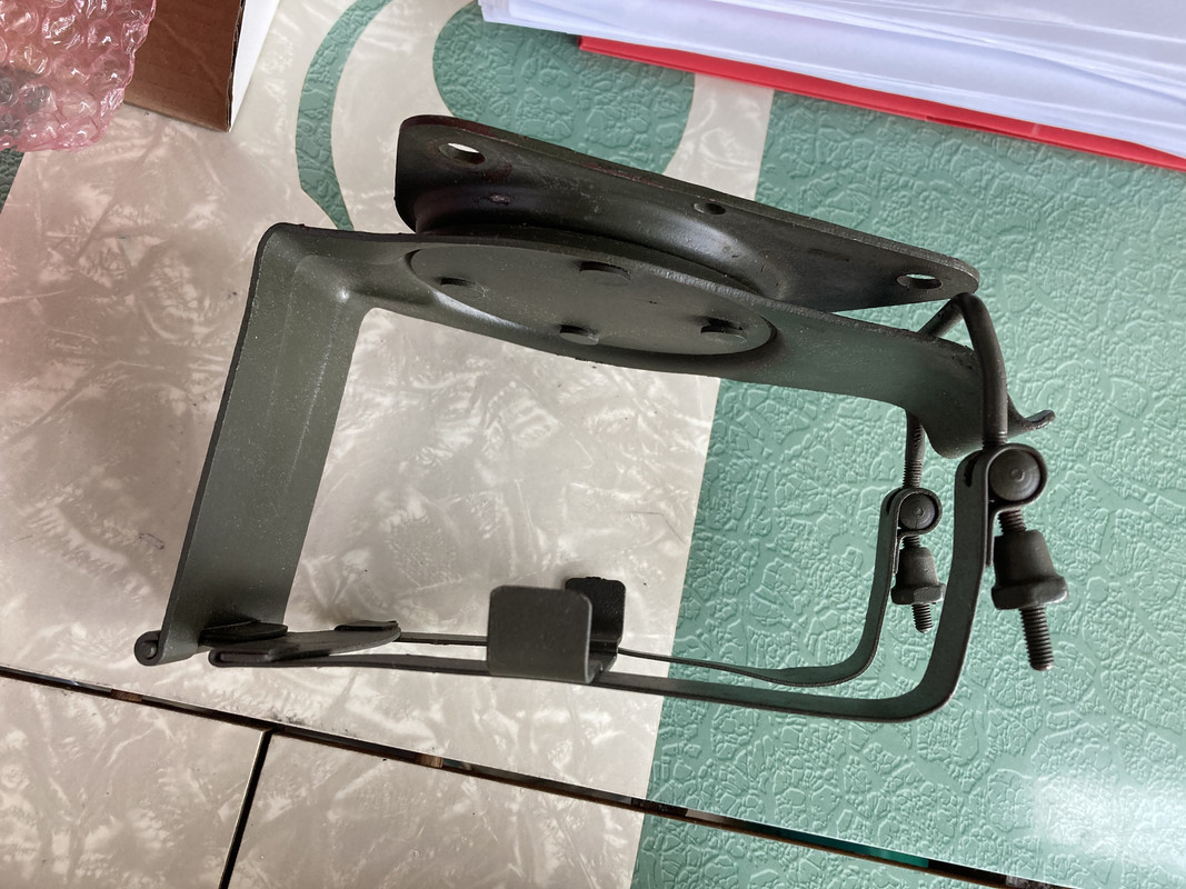
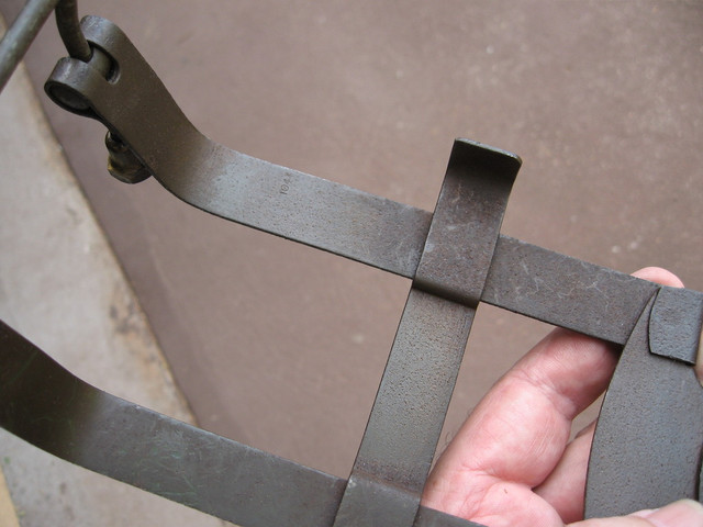
I was searching for the long bracket for the back side of the tool box . Everything I found was saying that its hard to find and people were making them themselves.... I saw the drawing with dimensions in the tech section here and thought OK that doable BUT I decided to search a little more and expand my criteria... Sure enough I found one in a box lot pile of seemingly junking stuff.. But there it was so I pulled the trigger... That arrived today as well. Mostly I can tell what everything is and what doesnt belong on a BSA.. But what is this ?
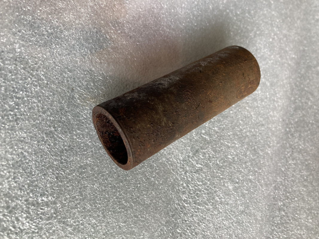
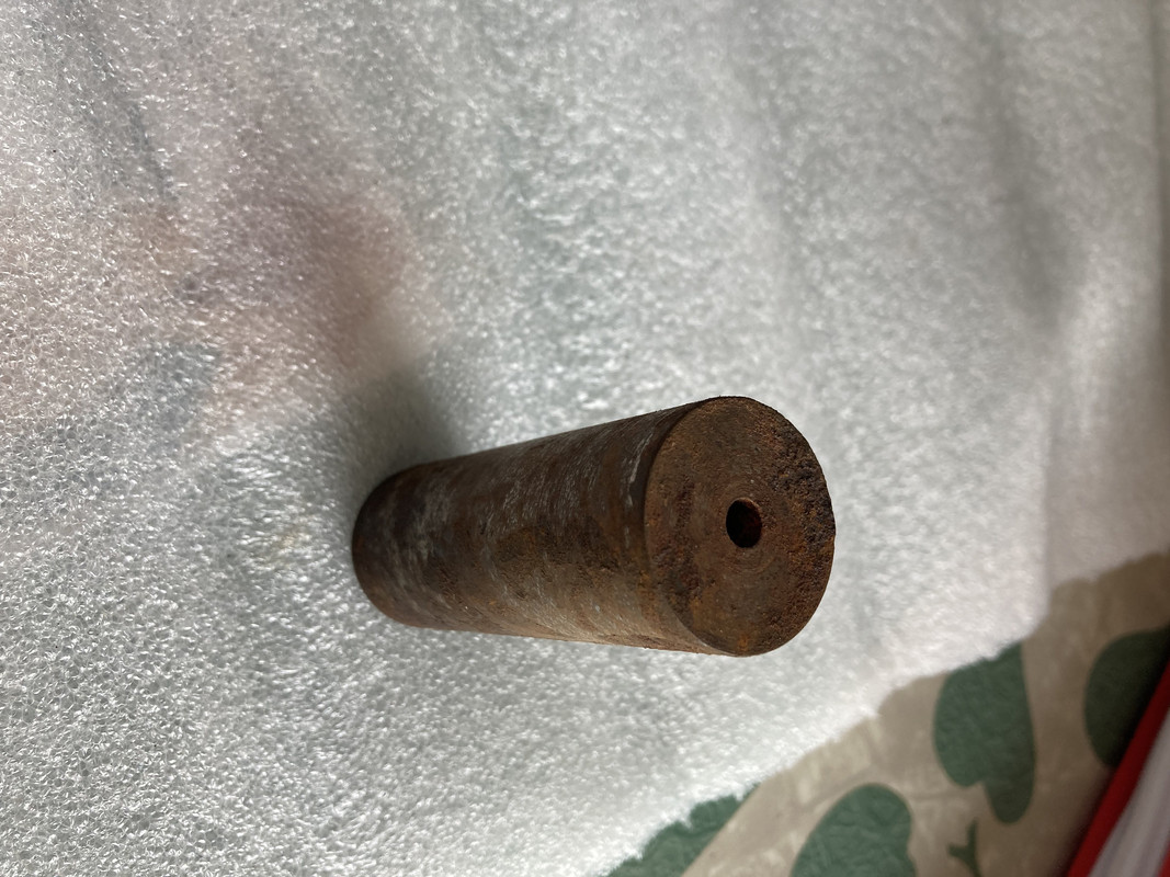
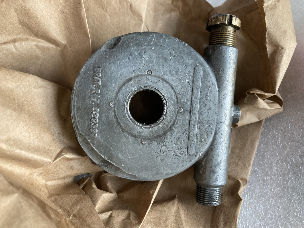
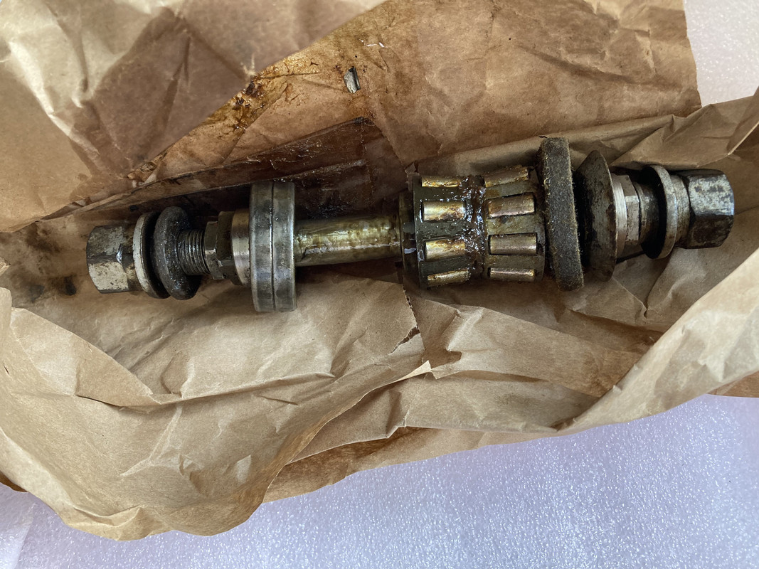
Also in a lot I saw this and took a chance. Looks right from the outside but Ill have to figure out if it spins backward like it should... And its missing the screw on top that hold the gear in place
email (option): wadeschields@mindspring.com
There is a good chance that the nut is in the oil tank, along with a small steel plate with two holes and a dimple which normally ensures that the breather remains open. There is usually at least one gummed into the gunge at the bottom of old oil tanks !
The other piece you asked about is a screwdriver bit.
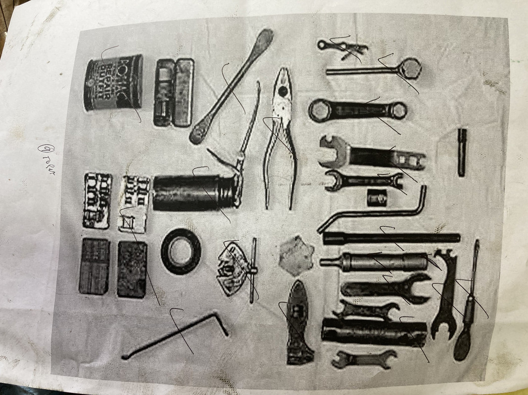
Tool ID here. http://www.wdbsa.nl/tools.htm
ron
email (option): ronpier@talk21.com
email (option): wadeschields@mindspring.com
Tool ID here. http://www.wdbsa.nl/tools.htm
ron
email (option): wadeschields@mindspring.com
Correction !! I continue to learn.. Or spend too much time on line researching :/
I see now that its a grease fitting missing on the speedo drive
email (option): wadeschields@mindspring.com
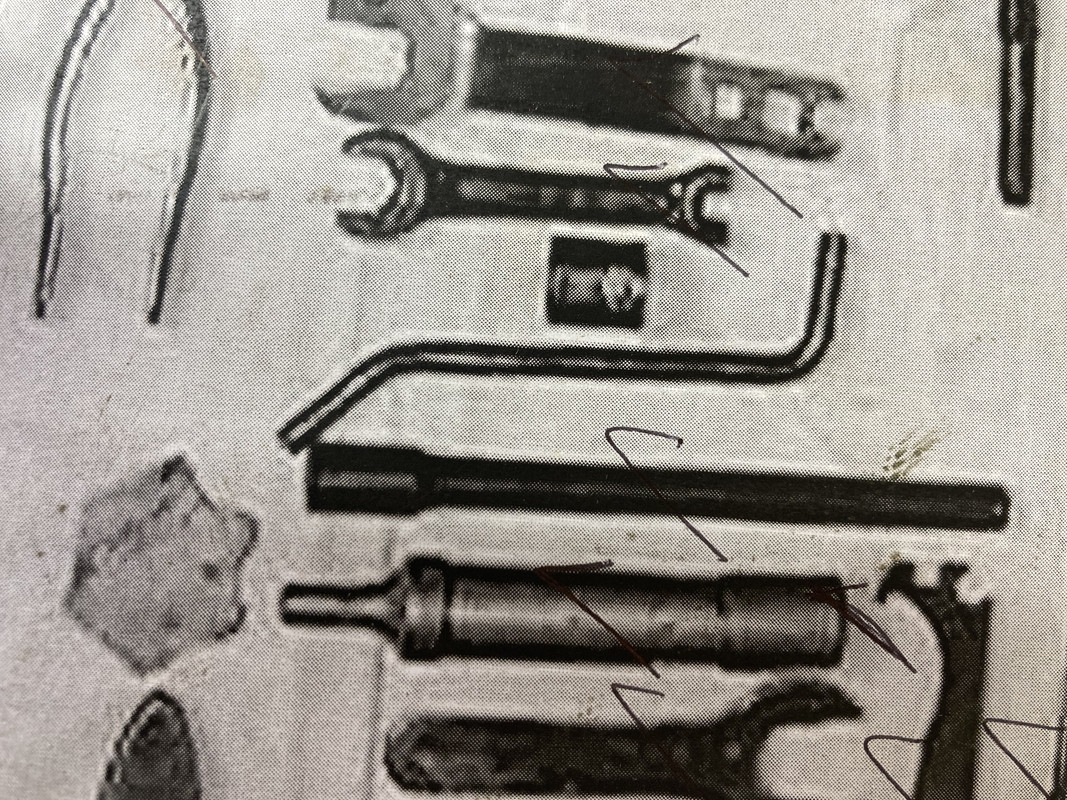
The bent bar is a tommy bar to use with the tube spannar above it and secong from the bottom
The odd shaped sort of triangle is the wheel alignment tool
make one the dimensions are in the manual and the pats book , both in the tech section.
Battery box is a repo .
Hi Wade,
I noticed that not all tools are from the correct model/shape on the photos you have printed out, f.e. the Romac tin is not the correct one and the same applies to the screwdriver.
The photos on this website show the original correct tools which should be present in a M20 toolkit: http://www.wdbsa.nl/tools.htm
Regards,
Bastiaan
email (option): wdmotorcycles@gmail.com
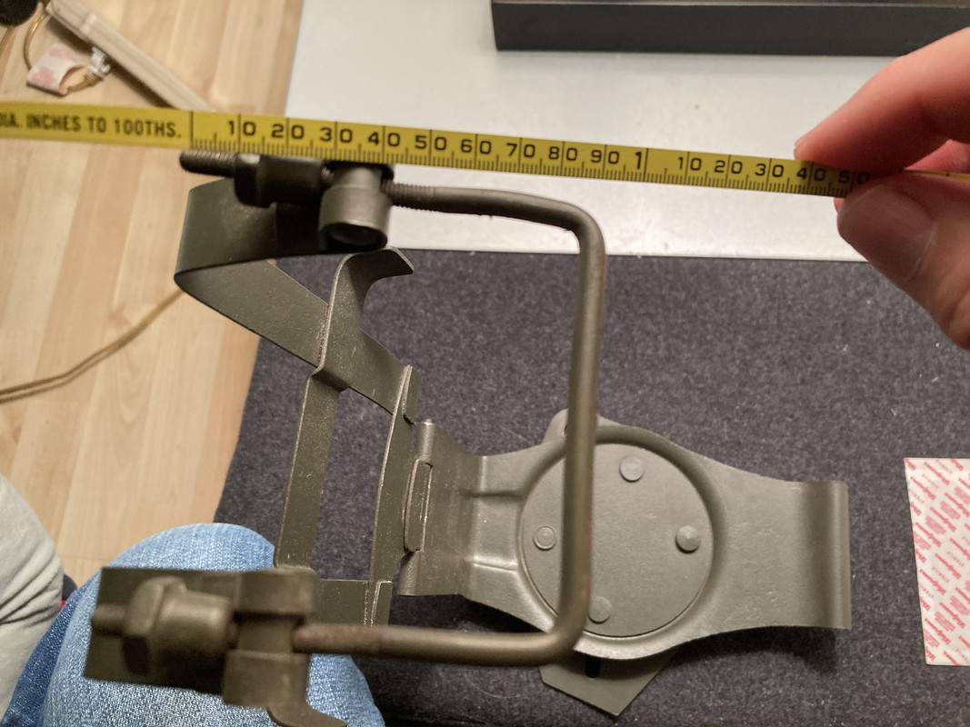
Wade, that battery carrier does look correct I think. It is a little bent up but appears to have the correct brass nuts on the upper clamp and the correct looking mounting bolts on the rotating bit at the bottom.
This is the later pattern with the cross bracket spot welded in place - the earlier ones that I have seen without that cross bracket spot welded have Lucas stamped into the hinge.
One thing that you might find is the manufacturing date code - on mine (10/44) this was on the inside of one of the vertical straps in quite small print. This was a NOS one I located some years ago and the corrosion dimples under the paint look very similar.
I just took a photo of an oil tank cap pulled apart to show the small piece that sits against the under side of the cap to provide a cover over the breather. It wouldn't be too hard to replicate if it is AWOL - let me know if you need specific measurements.
I make the finer thread for nut/splitpin as 1/4" x 26TPI.
email (option): rays54@hotmail.com
That is extremely helpful . Thanks for the photos
I dont see any date code on the battery holder so maybe it is a repo like someone previously stated.
A pretty good one I think for the price. I was wondering why some had Lucas printed on them. Now I know .. Thanks for that too.
email (option): wadeschields@mindspring.com
Interesting, that is streets ahead of the Indian made repros I see around the swap meets here - with a tiny bit of tweaking that would definitely do the job and look the part.
These are two remnants of the straps that have the Lucas stamping in place. I had always assumed this stamping was dropped with the later type but given I was mistaken about this repro then perhaps that is incorrect.
The earlier straps without attached cross piece were used with the Ni-Fe batteries as shown here.
It appears that when used with the smaller lead-acid batteries there were loose horizontal brackets used and these were spot welded at some point but I don't know when that later style was introduced.
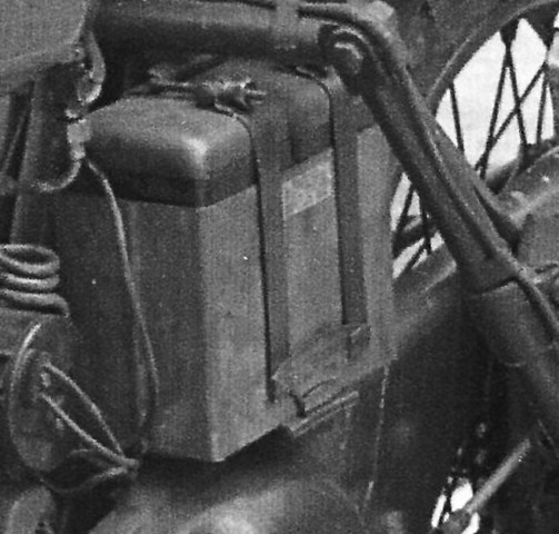
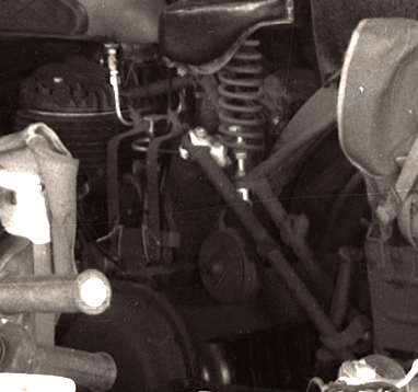
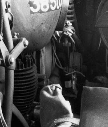
These grainy expanded sections of a photo of a batch of new WM20's delivered to Australia in WWII show the bikes delivered without batteries fitted and the bracket held in place with pieces of string/cord.
email (option): rays54@hotmail.com
Thanks for that info Ray and everyone.
Went up to my local brit bike shop here in the East Village tonight and showed them my pile of goodies I got with the tool box bracket. After a little discussion and some end of the work day beers we focused our attention on the speedo drive in the pile... The thing seemed frozen solid but with a little heat gun action it freed up and then I put the worm gear back in and checked the rotation. With the drive in the position as it would be on the front wheel , spinning the internal drive bit with the two nipples clockwise , the cable also turns clockwise. From what I am reading here that is correct rotation direction for the WM20 right?
email (option): wadeschields@mindspring.com
That sounds like your punt on the speedo drive paid off.
Make sure you have the washer fitted to the inner recess of the speedo drive (66-5524, Front Hub Washer (Speedometer Drive)- 0.640” x 0.950” x 0.078” thick)as the centre of the drive can be easily deformed if it isn't in place.
It is item 46 in the drawing Ron posted in a recent thread.
http://pub37.bravenet.com/forum/static/show.php?usernum=3155626639&frmid=16&msgid=1455380&cmd=show
email (option): rays54@hotmail.com
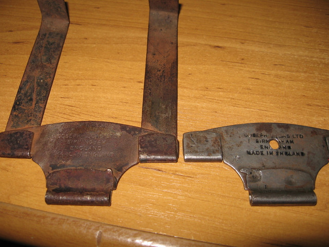
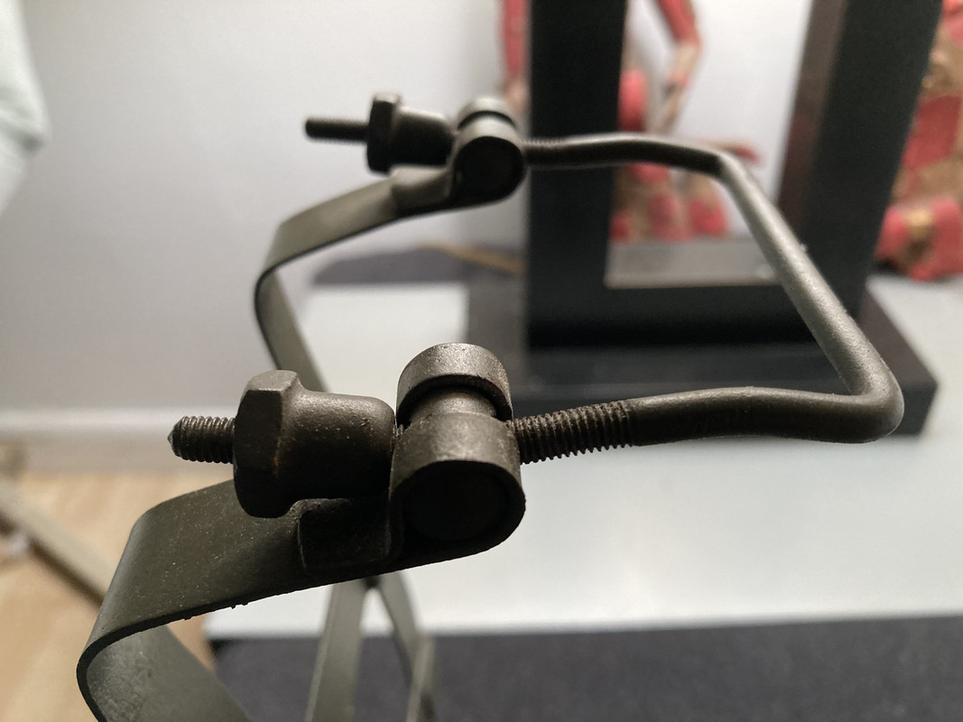
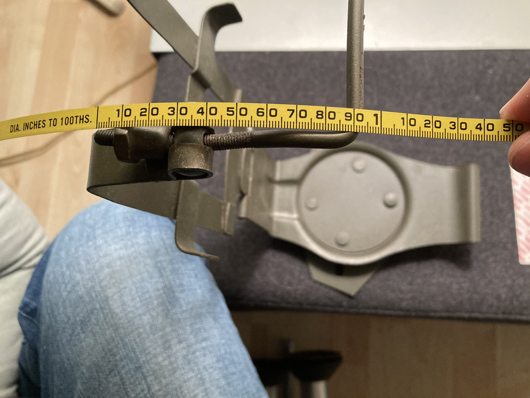
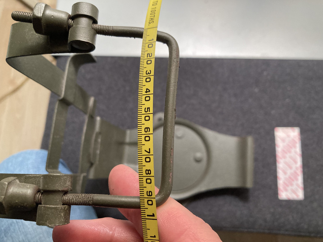
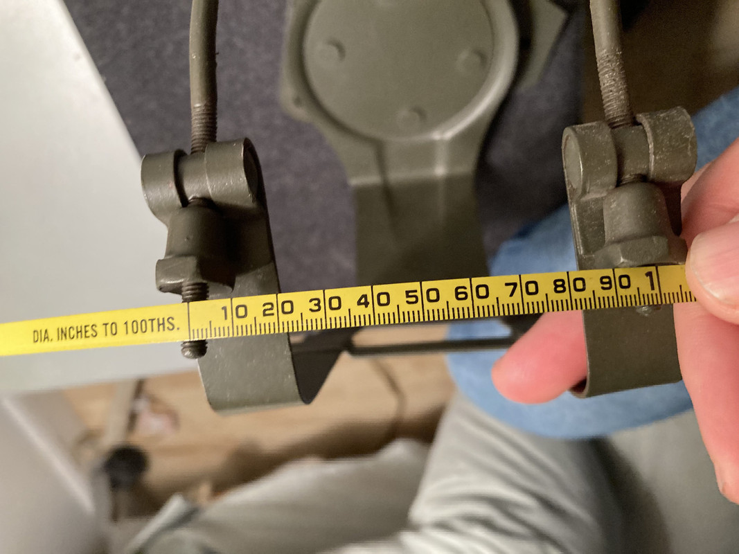
My Battery carrier is missing the threaded part at the top , so will make one for now , can someone tell me the length of the bar , from the right angle to the end of the thread ?
Thank you
email (option): ianacott@hotmail.com
Thank you
Assuming mine is correct of course.
You can see how far back the threads go too
email (option): wadeschields@mindspring.com
Metric ? :astonished:
Get Thee behind me, Satan ! :imp:
:grinning:
Get Thee behind me, Satan ! :imp:
:grinning:
email (option): wadeschields@mindspring.com
The bar is 3/16". The threads and for the acorn nuts is 3/16" BSF. Ron
email (option): ronpier@talk21.com
Thank's that's a great help :+1:
email (option): ianacott@hotmail.com
While we're rivet counting... Some more details about the battery carriers. The pictures below show the carrier that was used for the illustrations of the WD/C parts catalogue (1940), and a works photograph of a WD/C:


And these are works photographs of some WD/COs (1942 onwards):


Some remarks:
- It is clear to see from these pictures that the two straps on the later version (the changeover must have taken place in 1942) are about an inch longer than on the early version.
- The threaded rod on the early version is straight, the later version has a threaded rod with two kinks.
- On the early carriers the lip of the hinge, and the lips of the straps have been hemmed on the outside of the carrier (first picture). But I have several pictures of late carriers where these lips are hemmed towards the inside (second picture). Small mistake during the production I guess... But I don't see the Lucas text on the "faulty" carrier... Because it's mounted the wrong way round? The text is on the inside now?
email (option): wd.register@gmail.com
I have made a few comparison photos of the early and late battery carrier a few months ago. Both carriers are original and the differences in the shape of the backplate and the front part are clearly visible. What I have learned so far that is that it's not a good idea to mix a late rear backplate with an early front part, it's impossible to fit a NIFE battery.
Bastiaan


email (option): wdmotorcycles@gmail.com
That's an interesting comparison Bastiaan! I knew that the hook at the back was also different, but the Royal Enfield pictures weren't very clear in that respect. Now I see...
But... If you take a look at the parts catalogue picture, the hook is like on your black carrier. And if you take a look at the WD/C works photograph, you will notice that the hook is as on your brown carrier! Looks like a "hybrid" version: "early lid" with "late hook". And even Ray's picture with a NiFe battery has the "late hook"! Another mystery gentlemen! :wink:
Jan
email (option): wd.register@gmail.com
My impression is that if fronts and backs were to be mixed and matched, it would be necessary to have an appropriate hybrid hook.
In terms of how the fronts are welded, presumably this was done while they were still flat and they were then taken at random and folded for the trunnions with no regard paid to orientation. Presumably still lots of semi-automation and not a continuous process where the part remained clamped.
Standard practice in the UK ( for way too long ) was to make each part often on different machines then toss the different parts into stillages till needed then assemble as required.
Takes way too many man hours like this but aa lot easier for production scheduling back in the pencil & paper days
I noticed this when I was having problems with 4 spring clutch pressure plates dragging
So I could never to lift clean whie othere were set & forget
A polish & etch revealed totally random grain opientation with respect to the spring & pushrod holes as would happen if the blanks were cut then tossed into an open bin and the same happened during pressing & punching
Picked up some new parts
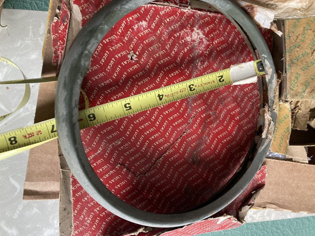
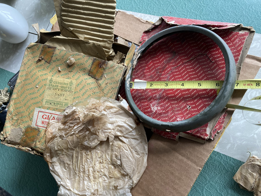
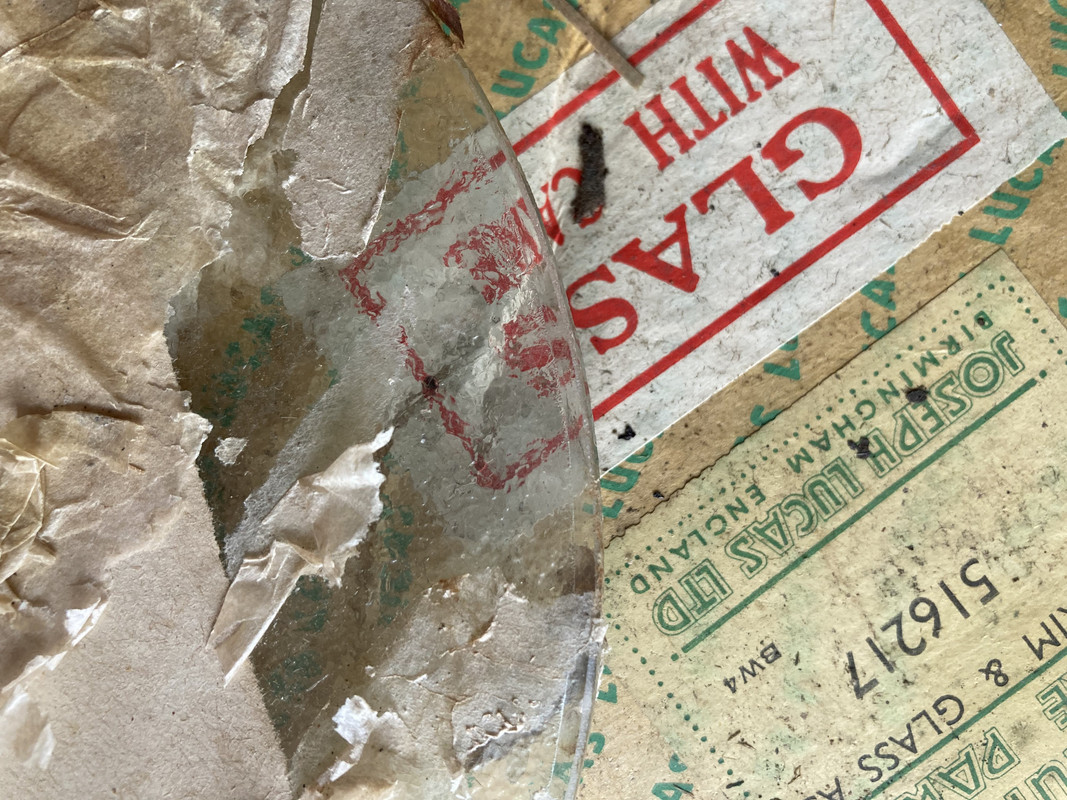
NOS headlight rim and glass with clips in packaging. two different styles of packaging ??
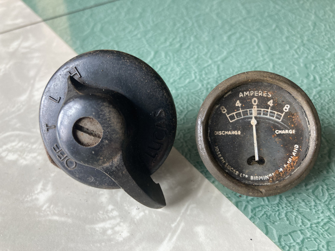
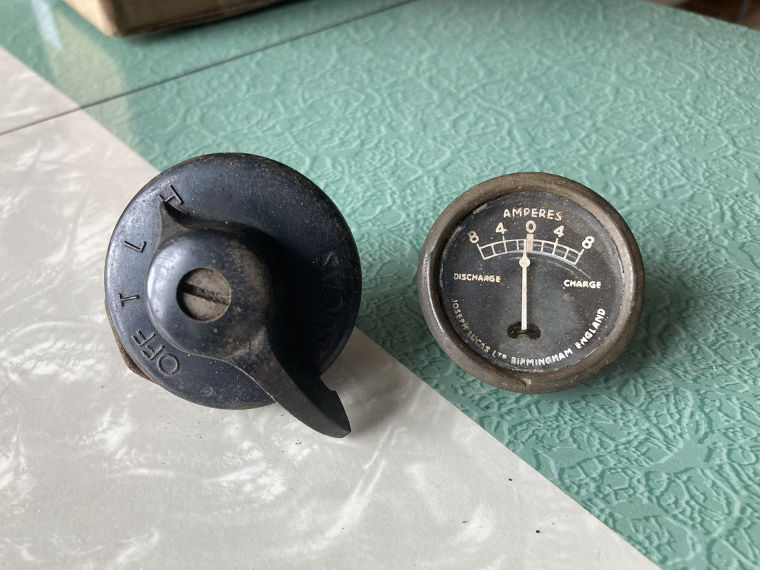
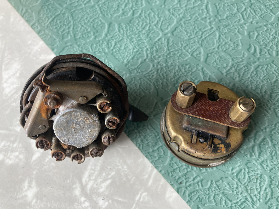
And hopefully correct Ammeter and switch.

email (option): wadeschields@mindspring.com
Any chance of a new thread?...Out in the sticks my computer speed isn't the best and it now takes about a minute just to scroll down this lot.....Ian
email (option): ian@wright52.plus.com
email (option): wadeschields@mindspring.com
Yes Wade by far better and just like on BritBike put the problem in the thread title so it makes searching easier .
The switch belongs to a bike that does not have an amp meter fitted.
The T position is Test which hooks one of the lights directly to the dynamo to check the dynamo is generating .
As for the rim that is for the 7" lamp.
Most Du42 headlights were 8"
Army headlights have a claw under the rim that grabs onto the outside of the rim
latter civilian rims have a hole in the top for the securing screw
The switch is the 'standard' military switch used for most of the war on bikes fitted with an ammeter...The 'T' position denotes 'tail light only' for use in convoys...
Later bikes had the different switch without an ammeter...
DU42 headlamps were 6 1/2"...The DU142 was the 8" version....From your measurement and the 'returned edge' where the rim is bent back at an angle to sit against the flat glass I'd say that is the correct rim, assuming it fits your headlamp shell!...Ian
email (option): ian@wright52.plus.com
Trevor is confused! The switch he mentioned has TEST written on it. As Ian said, your switch is the standard WD switch. The wiring diagram is clear how it works for the tail light only function via the brass butterfly flappers.
Your ammeter is also the correct CZ(Centre Zero)27. Ron

email (option): ronpier@talk21.com
Appologies to Wade for givin him indigestion
and thank you gentlemen for correcting me
Interesting I had some supposedly NOS military switches without the butterfly on the top
Where as all of the A series ones I have do have the butterfly .
and thank you gentlemen for correcting me
Interesting I had some supposedly NOS military switches without the butterfly on the top
Where as all of the A series ones I have do have the butterfly .
email (option): wadeschields@mindspring.com
Your headlamp rim looks right to me. It's the flat glass type and has the hole and lump at the bottom for the DU42 spring clip. Ron
email (option): ronpier@talk21.com
Go for it Wade..Start a new thread, it took me over two minutes to get to your last post and about 5 seconds to read it....Ian
email (option): ian@wright52.plus.com