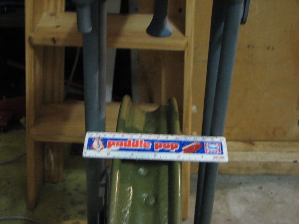
We have been discussing M20 girders in a previous thread. Today I removed the forks from a spare M20 that I have. By drawing a straight line on a piece of 4x2, and by laying the forks on this line with the top grease nipple and mudguard fixing stud as centres on the line, it is easy to measure from the line to each side of the forks.

In this instance everything measures exactly equal, which is not what the line drawing shows.

Also by putting a straight edge through the wheel spindle slots and then lining up an engineers square with this straight edge and the centre line. I was able to see that the wheel spindle is directly at 90 degrees to the forks.
If anyone else has spare forks hanging on a nail? Perhaps you could do the same and come back with comparisons. Ron
email (option): ronpier@talk21.com
If, as someone suggested on the earlier thread, an off-set was built in as a result of the change to the spindle-mounted speedo drive (rather than in the brake plate) then there is a good likelihood that there are some real miss-matched components around.
Based on my understanding of later telescopics, the brake plate side is usually the datum. Your rim off-set needs to relate to the centre line of the frame, not necessarily to the centre of the forks (unless they're an early set that may have been bent apart to take a later drive, then who knows what's where ?)
Could your tyre wear just be the result of road camber (or that ride back from the pub trying to stay on the tail of an oozlum bird )
)
hi ron,i can do that for you but not until monday now.
looking at the drawing you have posted there seems to be a slight offset at the top of the forks also.may just be badly drawn.i cant read the drawing dimensions can you clarify them?
also if you centralise the top bushes with your centre
line does that make a difference?the spring arrestor
looks well off centre,the grease nipple may not be a true centre but the mudguard stay is.
cheers rick
email (option): richardholt@rocketmail.com
the spring mounting spindle is not inline with your centre line drawn on the 4x2 its bent over to one side
email (option): roger.beck@node6.com
Rick that would be good. Monday is fine. Despite what the photo looks like ( because I didn't get a straight on picture) It is dead centre. The top grease nipple is dead centre of the forks.
Rik I agree with your thoughts about the different speedo drives used, which is why I'm interested in others contributions. Ron
email (option): ronpier@talk21.com
Hi Ron, I also have two sets of forks out of frame back home in the UK. I will not be back in the UK until this coming Wednesday, but will gladly check then. One is M20 ( 1938 ) and the other Empire Star ( 1936) both with the earlier offside speeedo drive.
Rgds dave
email (option): d.weston@virgin.net
I have checked my 1935 fork blades they are 2"1/2 on the brake side and 2"3/4 on the speedo drive side. The wheel does not sit centre in the forks being closer to the fork leg on the brake side. I have just bought another m20 1941 and checked my mate's m20's and have found all wheel sit closer to the brake side. The 1935 forks are not suited for a speedo drive. So I am trying to cut spaces down and edge a bit off the forks to make the m20 1942 wheel fit. I hope it will ride ok. thanks for opening this topic
That is very interesting Bryce. Both my M20's have the wheel nearer the right hand fork leg. I wondered how they could both be wrong. So it would be interesting to see if others could take a quick look. No need to measure anything....just stick a finger down each side and see if it's different. Ron
email (option): ronpier@talk21.com
Hi Ron
measured my forks today using the same method as you. Mine were identical to yours. My wheel is offset to the brake side by a bloody mile. I suspect the wheel is not original though, and I have been on the lookout for a new hub (mine is shot)and re-lace it correctly.
WM20-109711
1945
Cheers
Phil
email (option): wpgarage@xtra.co.nz
Thanks for that Phil. I'm a bit baffled by all this. Most forks that I know of so far are not offset (as the line drawing) Other guys are telling me that their wheel is closer to the brake drum side of forks than the other side. The offset of my wheel measures near as dam it to the spec given in the BSA standards book. In fact if I adjusted my wheel to exactly the standards spec, it would be even nearer the right side leg??
Ron
email (option): ronpier@talk21.com
wouldnt the rim be equal distance from ether side of the forks because thats what the offset is for to line it up
email (option): roger.beck@node6.com
Measured my fork today, and that gives 2 9/16" on the brake side, and 3" on the left side; total space between fork ends thus 5 9/16" but remember that my WDM20 arrived in a container with scrap from Egypt...
Can't read the dimensions on the sketch; anybody has a clue what it should be?
email (option): viaconsu [at] planet [dot] nl
hi ron,checked a pair of mine from centreline
left side 2 17/32, right side 2 11/16
giving a total gap of 5 7/32.
cant read the dimensions on your drawing so cant compare
the top dimension on mine is 4.680 which is about .007''
down on the drawing,not bad for seventy years.hope this helps cheers rick
email (option): richardholt@rocketmail.com
Thanks chaps. My best guess at the drawing figures are
2 19/32" and 3 3/32" Total 5 21/32" ? Ron
email (option): ronpier@talk21.com
I wonder who is most wrong: Rick or me...
email (option): viaconsu [at] planet [dot] nl
Hi Ron
This is an early short set also listed for the RAF combination stamped with the part number 66-5014.
Rob


email (option): robmiller11@yahoo.co.uk
Rob yours are definitely offset and look very close, if not spot on to the drawing. Ron
email (option): ronpier@talk21.com
hi ron,looking at robs photo,in the second one,its a pity you cant see both sides of the tape.also (im not being critical here) his centreline is about 1/8 ''
wide so how do you read that?
i marked a line on a marking-out table and set the first pair to that ,and measured with a steel rule.
i have just measured two other sets but not to the centreline,just across the fork opening one at 5 9/16''
one at 5 3/4''.i think that in all the years of service
these things have took some batter.im not going to do the trigonometry,but say fork the ends were say 1/32''
worn to each other in relative distance to the centreline,the amount of tip over to the opposite side would be considerable at 8 1/2''radius,just to the wheel rim,add the tyre and it will be more.
im not suggesting you do this but a bit of filing in the right place may or may not bring the wheel back where it is supposed to live.i remember 40 odd years ago making a rear wheel gauge to the bsa drawing.
i think there were three separate radi on it? so what was the third one for?.
i hope there is an answer to this because i will be starting building shortly,and i dont like doing things
twice,keep em coming every one so we can iron this one out
cheers rick
email (option): richardholt@rocketmail.com
I'm afraid it's me..
I think both fork legs are bent to the left, Don R not watching that German Tiger coming from the right. The fork looks allright, no damage can be seen, and the wheel goes easily in.
Have to think what I shall do; finding a way to secure the upper part of the fork, so I can pull the legs in the proper position.
(I mean the FORK legs)

email (option): viaconsu [at] planet [dot] nl
I did wonder about that operation myself Hans, if the situation arrives when I check the forks on my road going M20.
I was thinking about simply clamping a wheel spindle lug in a vice and see if normal arm power could pull the leg over. Gentle tweaking and measuring until it is correct. Then repeat on the other leg. But I'd be interested in your method. Ron
email (option): ronpier@talk21.com