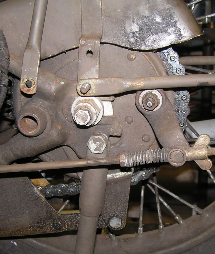
Installing the new carrier I have a problem with the bottom stay; it touches the top of the brake lever, and I cannot fix it the normal way:

Moving the brake plate assembly clockwise a bit would solve the problem, but how? The chain has normal play.
What can I do


email (option): viaconsu # planet dot nl
Hans, quick solution only if you have tried everything else is to fit a spacer to clear or shorten & re-drill brake anchor so it clears brake arm. Dave.
Send you an email,
Cheers,
Leon
Check the center to center distance of your Rear Brake Anchor Plate Strap (15-5816).
Mine is 14-3/4 inches and fits fine.
Cheers
email (option): britool51@hotmail.com
Thanks Robb, I'll try that!
PS: Is that total length or from hole to hole?
email (option): viaconsu # planet dot nl
HI Hans..'center to center'...the distance between the centers of the holes...Ian
email (option): ian@wright52.plus.com
Hi Hans,
I'll send you an Autocad drawing of mine so you can either make a new one if need be or alter what you have.
Cheers,
Robb
email (option): britool51@hotmail.com
Thanks Robb, I think that slowly slowly you'll get the whole M20 on AutoCad! I used to work with the younger brother, AutoSketch under Win95, but that is no longer available. And AutoCad is way out for me!
email (option): viaconsu # planet dot nl
Hi Robb... When you are putting parts onto a cad drawing how are you addressing the question of tolerances?...Do you follow normal practice and apply a 'general tolerance' and then apply specific tolerances when required..or do you just draw them dimensioned but without tolerances?
This is relevant if the drawings are to be used at some point for remanufacture of components.
Also have you specified materials?...Ian
email (option): ian@wright52.plus.com
Hi Ian,
I'm making the drawings sans tolerances and measuring as close as my tools allow. At one time I had all the cool stuff available to make detailed reverse engineering drawings, but no longer.
With the sheet metal parts, spacers & bracketry lose tolerances are OK. (Loose being plus or minus 2 thousands of an inch.) I could use todays Geometric Tolerances, but I'm also using used parts to draw.
I do not specify materials as I no longer work in a metals lab, and cannot get free analysis (damn!)
I have not done things like engine parts, gearbox parts etc as I have no way of deciding what the tolerances would be. I don't have the capacity to measure those, nor can I measure castings.
Have you any information on what standards were used back then? I'd sure love to have that. It would help me a lot.
Cheers
email (option): britool51@hotmail.com
Hi Robb..Standard practice in the UK (when using Imperial dimensions) would be to use what are called 'fractional dimensions' for work where a tolerance is not critical..For example if a brake torque arm was 14 3/4" long it would be marked as such on a drawing..ie in inches and fractions of an inch.
In that case no tolerance would be marked on the drawing but the tolerance applied would be the 'standard' one for a fractional dimension...that is + or - .015"
If the distance between the holes on the same torque arm was critical (for example) this would be marked on the drawing as a decimal dimension..ie 12.000".
This would then have a tolerance marked as well to tie the dimension down...ie..12.000"+ or - .005".
Any tolerance can be applied in this way to suit the requirements...it might be +.005" -.000" for instance. It was always stressed when designing/drawing components not to 'over tolerance' them..in other words not to apply uneccessarily tight tolerances. This was regarded as a fault that increased production time, complexity and cost and you were expected to think through the function of the component and each dimension and tolerance it accordingly
A tapped hole would be marked..'Drill and tap 5/16" dia. whit thru'..a drilled hole 'drill 5/16" dia thru' or a drilled and reamed hole 'drill and ream 5/16" dia. thru'...'thru' being the abbreviation for 'through'
A blind hole would be marked..'drill 5/16" dia by 1/2" DP' for instance,..DP being the abbreviation for 'deep'.
A radius would be marked with an arrow from the center point to the radius and dimensioned...eg..'1 1/4" R' or the word 'radius'
Other standard markings on engineering drawings would be 'Break all sharp edges'..which means deburr by one method or another. Or for a chamfered edge..'Chmfr 1/16" wide x 45 degrees'...
If a particular surface finish was required this would be noted adjacent to the component diagram and would specify 'turn' 'mill' or 'surface grind' to a specified finish. If this applied to only one surface this would also be noted.
Material (Matl.: 1/2" dia. BMS bar(Bright Mild Steel) (for example), along with hardening spec., oil blacking, plating etc. etc. if applicable) would be in a 'box' in the corner of the drawing along with the date drawn and the draughtsmans name. Modifications to any drawing would also be recorded in a seperate 'box' with the date and the draughtsmans name.
At the top of the drawing would be a component 'title'....Ian

email (option): ian@wright52.plus.com
Yes Henri, just a couple of millimetres difference, but enough to clear the stay!
I have the choice to add a half or 1 1/2 link to the chain, and re-adjust the rear wheel, or make another anchor strap using Robb's drawing... 
email (option): viaconsu # planet dot nl
hi hans,henri seems to have a thicker spacer between the frame and brake plate,could you try this,cheers rick  ps ive e-mailed you something rubbery
email (option): richardholt@rocketmail.com
Hi Ian,
Pretty cool to know. Thanks. That is also the case with many industries here too. For instance, I helped with design work on components to the Clean Room that the Hubble Telescope was built in. We would put in a note saying "Sheet metal tolerances" as they are much different than machined parts. We never let anything go beyond 1/32 of an inch. Being square was non negotiable.
Later, I worked for Pratt & Whitney in aerospace as a tool designer. Tool and gage tolerances are another animal all in themselves!
Break sharp edges was OK, but everything else had to be called out.
Well agreed on the thinking things through aspect. In the design classes I taught, I made my students write instructions on how to use what they drew. You should have heard the HOWLS of pain..... but, "This is COLLEGE!" 


For the fork links and bushings, I'd love to get my hands on a book of standards what REME would have used to determine wether or not to replace the parts.
Cheers
email (option): britool51@hotmail.com
I went to the shop and played with mine just now. I think that the rear fender stay should be OUTER most as the vertical stay, the lifting handle and the prop stand clip provide a lot of room to clear that cam nut.
Also, which way round is that stay? The flat is pushed to one side, and that can make a difference.
email (option): britool51@hotmail.com
someone on this forum reprinted a technical hand book inspection standards by s j madden i dont know whether there are any available now but i know there is some one on the forum will
Yes Steve Madden has a 1954 Inspection Standards Handbook which he kindly copied free for a few of us. It includes 1958 supplements. It needs someone with time and printing facilities to do some more copies.
Ron
email (option): ronpier@talk21.com


