
Hi Folks
Rik pointed out to me on a previous post that the part numbers in the Norton parts book for 16H valve guides are totally different for the inlet and the exhaust. I always thought they were the same:-
I've looked on Alpha Bearings website:-

and that shows the same OE part num for both guides for all 16h's, (incidently a different part num from the Norton book) but a different Alpha num for the 1946 to 55 16H's.
So whats going on, is it a typo in the Norton parts book??
So along with keeping the guide to stem clearance a secret Norton made sure you didn't know whether you had the right valve or not as well...and didn't put valve timing marks on the cams either just to be sure everything would be easy to set up correctly... ....Ian
email (option): ian@wright52.plus.com
They didn't want this information getting into enemy hands in case of capture, it was to be passed from father to son only

email (option): horror@blueyonder.co.uk
I don't recognise the part number that Alpha quote as OE at all - It's not Norton so perhaps from another after market supplier that Alpha took over the catalogue from.
The 1934 Norton parts list shows the guide, inlet and exhaust as part no. 9118. I believe that this book ran to the 1935 redesign. The 1937 book shows 3715 inlet and 8776 exhaust. This changed for the 1938 civilian models as they had the enclosed valves (no grease nipples needed). They then became 8932 and 8933.
I suppose the options are different materials, greater clearance on the exhaust or different form - either to improve gas flowing on the inlet or heat transfer on the exhaust guide.
Bearing in mind that none of the period literature (including that written by designer Edgar Franks) mentions reaming the guides to size, the implication is perhaps that they are pre-sized and it might simply be that the exhaust has a couple of thou extra clearance.
The OHV engines used the same guide, in. and ex. during this period.
If there is a critical difference then we are effectively playing a lottery when we fit new guides as the application of sod's law means that we'll never get two in the right place.
email (option): 79x100@gmail.com
Thanks for that Rik.
I think that's the most definitive explanation that there can be, but what it means is the whole thing is a nightmare. I suppose its just a question of collecting what bits you can and trying them out to see which works!! 
Regards
I think that's the most definitive explanation that there can be, but what it means is the whole thing is a nightmare. I suppose its just a question of collecting what bits you can and trying them out to see which works!!
Regards
I've done that three times over the last few years. The jury's still out on whether it's a good'un this time.

email (option): 79x100@gmail.com
I pretty much applied M20 valve stem to guide tolerances to Riks engine the last time...So .0035" clearance on the inlet and .004"-.0045" on the exhaust.
It appears that lubricant type has some effect as well but I don't know what Rik is currently using...or how frequently..I reckon a possible solution might be to throw away the grease nipples...arrange a metered (minimal) oil supply through the holes previously occupied by them and live with the resulting oil leak.....Ian
email (option): ian@wright52.plus.com
It's funny you should say that Ian, I was thinking the same thing. After looking at the total loss system on my Manx (and the oil that leaks everywhere) that is only some very thin copper tube pushed into a hole with a bit of silicome around it. It must be possible to rig something up the same for the 16H.
email (option): horror@blueyonder.co.uk
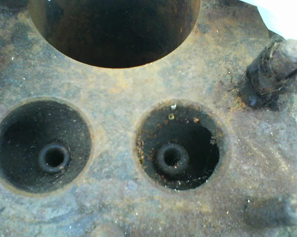
OK, that's a fib...I don't claim responsibility for that soldering job...and I don't know how the exhaust port got burned away.
The feed for this system seems to have replaced the cylinder wall oil regulating screw on the top edge of the timing cover. I'm not sure what the consequences would be of this.
...Oddly enough, these guides look different. The inlet is longer, thinner and turned parallel. the exhaust guide looks shorter, fatter and more of an as-cast finsh. I should knock them out and make a proper comparison.
I've seen both shapes before and assumed they were different batches...Hmmm.
email (option): 79x100@gmail.com
Ah good one Rik, you've had this barrel all along..?
I would have thought a T piece off the return would be a better place to take it from, and thinner pipe, as the large size would flood it with oil.
email (option): horror@blueyonder.co.uk
I forgot about it to be honest. I once bought a bottom end at Netley, late on the Saturday and the chap said that he'd knock a fiver off if I took the scrap barrels as well... I stuck it under the bench when I got home as I'm incapable of throwing things away.
The trouble with this mod is that it's a bit visible on the best looking side of the engine...but if it's the only route to reliability...
email (option): 79x100@gmail.com
I think a much more discrete set up can be worked out. If the guides were turned so the grease holes were facing backward, the pipe could go behind the valve cover and be unnoticeable. The feed on the Manx is 1/8" external diameter, so the internal must be about 1/16" or so. The Manx is pressure fed and the oil goes everywhere, but this size would be plenty big enough for a trickle feed from the return on a 16H

email (option): horror@blueyonder.co.uk
Hi Dave,you could use a drip feed oiler,concealed away under the tank,check them out on ebay to see what i mean,they come in various sizes and are adjustable as
to how many drips are required by turning a knurled knob then locking it off.
the flow is started /stopped by flicking the toggle on top to the upright position
or to the horizontal.just a thought
cheers Rick
email (option): richardholt@rocketmail.com
That's a good idea Rick, the cheapest on ebay is £5.88 with free postage
email (option): horror@blueyonder.co.uk
Hi Dave,i think it would work well if you can conceal it,or get a nice brass one
and tuck it away near the battery or somewhere.They are pretty robust and can be regulated down to a very fine amount.Im glad i looked on that page myself,i have worked lathes for over forty years and never been able to find out what the hole
in the tailstock was for.Now my quest is over,its for a"Sam Lee"on the same page
360038989196
cheers Rick
email (option): richardholt@rocketmail.com
Hi All
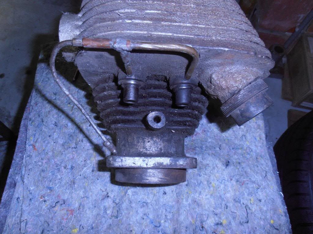
Right I've dug out from the darkest recess's of the shed a NOS barrel complete with factory fitted valve guides. Its never been near a bike in all its 70 years!
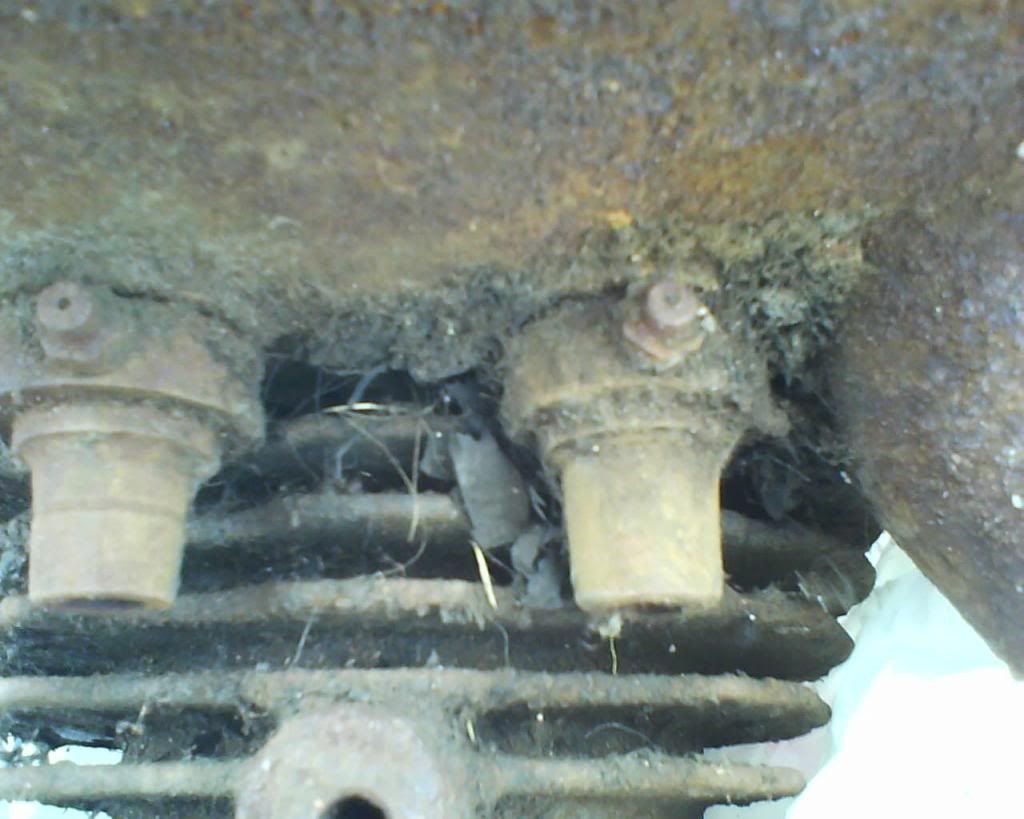
As you can see the inlet guide is tapered whereas the exhaust isn't, it also has a groove machined on it!
The mystery deepens!!
If that's never been fitted you should clean it, blast it, measure the valve guide bores and compare them to NOS valves, to determine what the original stem clearance was...Nobody actually knows that figure and it isn't in any Norton publications that have come to light so far...Presumably if that was a replacement barrel the valve guides have been machined to the finished size after fitting to the barrel....Ian
email (option): ian@wright52.plus.com
Yes Ian, I had 2 of these the other I cleaned up, painted and its now done over 2000 miles on the bike. All it needed was a 2 thou hone to get the piston clearance correct and a pass over the valve seats with a cutter before grinding them in. I just popped the valves in assuming, as you say, that the guides had been reamed in the factory. They were ex army spares sold on after the war.

And Horror will have to take another 'Thou' out of his exhaust guide when he races the Model 18. :relaxed: Ron
email (option): ronpier@talk21.com
Aah the Holy Grail has been found! However note the ignition timing is given as 3/8th whereas the Maintenance Manual gives 7/16th. So manufacturers figures???
Edgar Franks gives 3/8" BTDC in his Norton maintenance guide, in a table which says that it refers to 1932 engines and all subsequent unless amended later.
The late 1930s instruction books though give 7/32" which is a huge difference. Was it a miss print which was never corrected ? It would seem incredible.
Wartime use of compression plates and decreasing fuel quality may be the factors here. Whatever, I'm pleased to have found at least some info referring to valve stem clearances.
The exhaust guide in the M20 is longer than the inlet and the top 5/16" or so is counter bored to about .040" oversize (that's an approximate figure subject to accurate measurement) to prevent friction caused by contact between carbon build up on the valve stem and the top of the guide...
Interestingly, heat transfer from the valve head (which is red when running) through the stem to the cam followers must have caused problems with wear at the foot of the follower as the follower foot is hard chrome plated (the inlet is not)..Presumably the heat treatment was affected...OHV engines such as the B31/33, which have pushrods, do not have this treatment applied...Ian
email (option): ian@wright52.plus.com