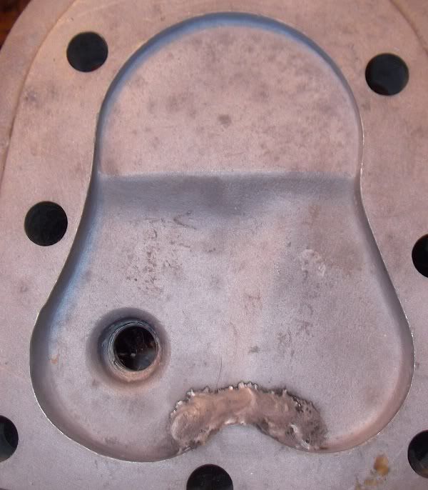
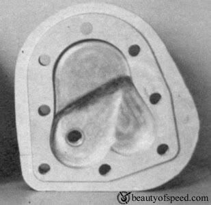
We have lots of spare heads to play with, so i did a rough copy of KH pattern head fill with mig and some dremel work and "WOW' what a difference.It now accelerates up hills! No pinging and cruise at 60mph per.Any Oz doubters are welcome to test ride! We will try some compy cams next!
Interesting stuff Douglas, have you worked out what compression ratio you are getting up to?
I hadn't realised that the M20 head has a bit of squish going on to one side (shows up in the engine section on Dannys Wet Sump thread, plus your pics) and yet the 16H without this seems to have at least the same performance - from what i have read anyway.
Iain
The 16H has a dome top piston Ron
Ron
email (option): ronpier@talk21.com
There are actually two different M20 heads, I have both but the unusual one is in use on my bike and I am not going to remove it  The shape of the combustion chamber is quite different. No idea what the reasons is as I didn't notice anything when I replaced one for the other.
Henk
email (option): ahum@quicknet.nl
The 39 spares list says the M20 and M21 had different part numbers for their cyclinder heads, M20 66-94 M21 66-96. And then the spares list's for M20 contract C7287 onwards have yet another part number 66-57, so it would appear there are 3 types of iron cylinder head
email (option): robmiller11@yahoo.co.uk
The practical limit for compression ratio is about 7:1...not very high but a lot better than the standard M20s 4,9:1...though care must be taken not to restrict gas flow when making alterations. If the plan was to go further than that then repositioning the spark plug and experimenting with timing settings would be necessary. With a sidevalve though high compression ratios are gained at the expense of gas flow so are not guaranteed to be beneficial. Late K model Harleys produced the most power but did not have the highest compression ratios. Sifton and others concluded that erring on the side of good gas flow (and cylinder filling) was ultimately the best course...there's no gain in a high compression if there's nothing to compress!
Early '10 bolt head' M20s retained the combustion chamber shape from the first '8 bolt' type M20 engines and although this is a different shape internally to later heads it is the same volume so compression ratio remained unaltered. Changes made to produce the later heads were done to improve combustion.
I am not entirely sure about the different number for the M21 head mentioned by Rob. I have only seen two types of head for later engines. However, their are two types of head gasket available for these engines and one of them is not suitable for use with either of the heads I have seen so far, so their is definitely a third type out there. (or 4th. type if you include the 8 bolt ones!!)....Ian
email (option): julie@wright52.plus.com
I have no idea what compression we ended up with but strangely kickover compression is much lower now. We could stand on it before. Any theories?
Douglas: 1. On the photo on your first post, what is that additional piece between the exhaust valve chamber and the intake valve chamber? What specs?
2. When you say your fill is similar to a KH head, do you mean the shape of the fill or simply the amount?
3. Does this work on iron heads, alloy, or both?
email (option): jonny.rudge@verizon.net
The divider was my own indulgence. KH's don't have that. Personally it probably doesn't do anything. Just fill the area above the piston to about 3/4 full and flush with that small squish area.The next head i will be more professional and angle the filled in area with the right amount of slope.I'll find some better pics.
the timing hole is blocked up do you change the head to time the magneto
Hi Roger..Douglas's last two photos are of a K model Harley Davidson head..which doesn't have that hole. I think they were just posted to illustrate the alterations to the head shape. In an M20 head the bolt enters the head on the part that foorms the 'squish' area over the piston so it is unaffected by the modification....Ian
email (option): julie@wright52.plus.com
I guess my only remaining concerns are whether the localized heat of the fill welding risks warping of the head, either when it is done or when the head gets hot on a long ride; and whether the larger squish area may cause pinging because the longer route the flame front would have to travel under "squish" conditions. But I guess that would have to wait for Douglas' further report after he puts a few more miles on the new motor.
email (option): jonny.rudge@verizon.net
Hi John..Distortion of the head during/after welding could well be an issue with the aluminium type but I have found the iron heads to be pretty stable.
Saying that there is plenty of material on the gasket face to allow for a light skim to true things up if necessary....I have done this many times.
Regarding 'squish' and flame travel the flame path will be shorter if the enlarged squish area is set up properly....that is the purpose of it. As the piston arrives at top dead center the gas is squeezed out of the squish area and concentrated in the now reduced combustion area, resulting in a more compact chamber with a shorter flame path and with less 'dead areas' of gas which promote uneven burning and 'pinging' or 'pinking'.
It is important though that the squish clearance (the gap between the top of the piston and the underside of the head at TDC) is not too large. It is generally accepted that the effect is lost if the squish clearance is more than .040".
In the M20 however, and other singles with a similar crank assembly, crankshaft flex must also be taken into account. Therefore the squish must not be set too tight either if piston contact with the underside of the head is to be avoided.
From my own experiments reducing squish much below .030" with the engine static is likely to lead to this problem when running.
So, if the piston is flush with the top of the cylinder at TDC (and this should be checked during assembly) fitting a .040" thick solid copper head gasket conveniently creates the correct clearance (there is little compression of a solid gasket when torqued down).
Composite gaskets are less predictable in terms of their final thickness after tightening down.
K Model Harleys didn't use a head gasket at all to enable the squish to be accurately held to the minimum clearance...they had the faces of the head and barrel finely machined and a single coat of aluminium paint served as a gasket/sealing medium. ..Ian
email (option): julie@wright52.plus.com
No distortion, but expect an alloy one will, but that would be machinable.Remember though that K models have there valves much closer to bore so M20's could never achieve the efficiency of them.So Ian have you a mig to experiment with?
Hi Douglas..I don't own a mig myself...just oxy-acetylene..but I have ready access to both mig and tig through a friend who is a welder.
I experimented reasonably extensively with head shapes and compression ratios during the enlargement process that lead me to my current 720cc M20.
This was partially to test the 'accepted wisdom' that sidevalves won't tolerate compression ratios beyond 7:1 due to pre ignition problems and restrictions to gas flow. I started off at 8.5:1 and progressively reshaped the combustion chamber and measured the CR at each stage,testing the bike on the same piece of road each time to gauge the results. I also experimented with various amounts of ignition advance at each stage.
Broadly speaking I would say the process proved the theory..at least with a fairly 'standard' overall layout such as you have produced with your current head.
It is worth noting here that I was limited in these efforts by the desire to produce an engine that was externally unchanged for use in my military bikes.
The engine I am now putting together is free of these restraints and I am being far more radical in the layout of the top half as well as having had cams specially produced for the sidevalve to a spec. I have concluded is the optimum. The cylinder head, which has not been made yet, will also be a one off. The piston is also a 'special' made by CP Pistons in the States. Valves are from Manley...also an American company. The conrod...which is also yet to be made will be from Carrillo Industries...I just need to get the £500 spare!!
This new set up is also scheduled for a number of sessions on a flow bench to get the best possible gas flow/port angle and position etc.etc...all good fun and a monumental waste of money!!  ...Ian
email (option): julie@wright52.plus.com
A bit more sophisticated than my method! By the way is there any common inner valve springs i could use off another make?
Hi Douglas...I ran inner valve springs in mine initally but have sinced removed them...not really necessary I don't think if the crank is at its standard weight and revs are not too excessive. However, I'm sure others would disagree!...Mick from Draganfly runs inners in his I believe. You can use BSA C15 inners or Ariel single inners such as WNG....Ian
email (option): julie@wright52.plus.com
Thanks Ian.
Hi Gents
Thanks Douglas for starting this thread.
With all the head work going on, is any one relaving around the exhaust valve. I have been advised to do so by a few older gents, To help prevent the exhaust valve from getting hot spots & burning out.If so what would the shape and depth be.
Thanks Michael
email (option): Michael@nammech.com.au
Hi Michael...The exhaust valve does not rotate when the engine is running so the side nearest the cylinder runs at the highest temperatures, as it is directly exposed to the outgoing exhaust gases.
Personally I don't think relieving around the valve (though I am not entirely sure what they mean by that) would be beneficial.
The M20 is not particularly prone to exhaust valve failure as long as particular things are attended to.
Sidevalves generally run hotter than OHV types but employ the same valve steels..consequently the margin of safety before valve temperatures become destructive is smaller.
For that reason it is particularly important that no condition is allowed to persist that has the effect of further raising temperatures.
So, it is important that ignition timing is accurately set and the bike is never run with the ignition retarded apart from at very low engine and road speeds.
Mixture should also be carefully checked to ensure it is not set too weak anywhere in the range and any sources of air leaks, which would weaken the mixture should be watched for. Leaky head gaskets, leaks at the carb flange, badly degraded valve seats and valve faces (air can be drawn in through the exhaust valve on the induction stroke) and leaks around the spark plug or timing access bolt. The latter should have an annealed copper washer fitted under the head. Also ensure there is sufficient tappet clearance and that the valve lifter is correctly set.
Finally there is the condition of the exhaust valve itself...this should have a quite wide 'land' around the edge and above the valve face. The purpose of this is to help the lip of the valve withstand the high temperatures. When new this land is approx .040" wide...if it has been substantially reduced by refacing the valve or excessive lapping it shouldbe replaced.
If all of the above are attended to you will find exhaust valve failure to be a fairly rare occurrence...Ian
email (option): julie@wright52.plus.com


